


© all rights reserved G W Howe 2017 - 2020
Articles
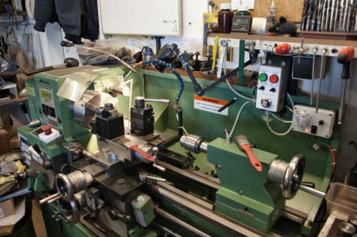
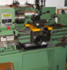
Article review of the BH600G Lathe & Modifications
GWH Engineering
creative engineering in a home workshop
The BH600G is essentially the same design supplied by
many different suppliers in various countries. That
said i am sure the place of manufacture varies as does
the quality and although the design is similar some
details vary. These lathes offer a very reasonable lathe
especially for the small home workshop and as sold
they include nearly all the essential bits that are often
only available at extra cost on non-Chinese lathes.
When I bought my Myford ML7 lathe in 1962 as new it
came as a very basic package, no motor, no stand, no 3
or 4 jaw chucks, no tailstock chuck, no fixed or sliding
steady rests, no screw cutting gearbox, no clutch and
no electrical safety provision or motor switching.
Build Quality: The BH600G is manufactured to satisfy a
specific market and that largely affects the quality of
manufacture. The Myford was built for a largely home market at a time when where there was virtually no competition and was
mainly aimed at the hobby machinist and so the design had many additional add-ons but all at extra cost! Without question the
Myford is manufactured to a much higher quality standard and in many respects hand built by experienced fitters. However, the
relative cost of a Myford is, in todays market at least 4 times more expensive than Chinese lathes of a similar or greater capability.
Design: The Myford unfortunately is from a design originating in the early 1950’s and very little was changed as the years went on.
The Super 7 provided more features like a gearbox, clutch and better bearings but overall it retained the same old design from the
ML7. By contrast the BH600G was also from a basic design but one which had taken advantage of modern production engineering
techniques and materials. For me the crucial change of design was the spindle through hole diameter as this radically improved the
scope of work that could be done.
Conclusion: I can sum this up by saying since I bought the BH600G 5 years ago I have used the Myford probably for less than 1 hour
in that time. But , in the case of the BH600G, you do have to check it out and many areas will some require re-work or better fitting.
The major consideration when buying the BH600G for me was that it was a very simple design and in most cases I could improve the
fitting of existing parts and should parts need replacing the cost was low. The critical areas of design and manufacture of any lathe is
the main bed ways, the spindle and bearings. Fortunately, I found these are all of a good standard on the BH600G, The ways are
accurately ground and hardened , the spindle is well made and also ground so that commercially available bearings are more than
adequate for home workshop use. It is interesting to note that in modern times the manufacture of bearings has radically improved
such that even standard grade bearings are of a very high standard when compared to 20 years ago. I was told by an engineer who
visits China that the machines used to grind lathe beds are very high quality and totally automated.
The rest of this article will describe the modifications and remedial work I have done to correct some of the poor fitting as supplied.
Stand & Levelling:
The stand unit as supplied is quite satisfactory but I fitted additional cross bars (12mm x 50mm) to give more rigidity to the
floor mounting points with extra width so that although free standing on a concrete base it has a greater foot print area. At
each end of the bars is a 12mm tapped hole for a bolt and locking nut arrangement so that levelling is easily done. The bolt sits
on an aluminium pad to resolve vibration issues.
Cross Slide and Compound Slides:
Unfortunately, these are not fitted that well. The taper Gib is a great idea but difficult to re-fit unless you start with new longer
Gibs and then scrape them to a precision fit. I did scrape them to ensure the sliding surface was flat and would have good
contact. The compound slide was a reasonable fit to start with so the scraping certainly improved matters. The cross slide had
a taper issue so I scraped the gib so that it was flat and decided to correct the taper problem by having 4 M4 adjustment screws
fitted to the side of the cross slide to locate back side the gib. This is exactly the same as used in a Myford which has parallel
gibs. This is a simple and effective solution and the amount of screw adjustment needed is minimal, probably 0.0001”.
Recently added a new quick withdraw action for the compound slide when cutting screw threads. (see link)
Tailstock:
The fitting of the tailstock to the ways was in my case poor. The amount of contact area with the ways was probably 10%. The
solution required quite a lot of scraping to increase the contact are to about 70%. That accomplished the tailstock had now lost
height and so 0.010” shims were needed between the sliding bottom block and the tailstock top. This is not an easy task and by
judicious scraping eventually the tailstock is within the stated precision requirements, actually better than as originally supplied.
This shows how poor Chinese fitting can be and how they get away with hidden problems, totally unacceptable but now
resolved. Tony Mount had described in Model Engineer mag. a modification to increase the clamping of the tailstock barrel so I
added that for good measure. A much better clamp.
Chucks:
I was very concerned that the 3 and 4 jaw chucks supplied would be low grade and probably need to be changed. On the
Myford I bought Pratt Burnerd chucks which were made to a high standard and also quite expensive! After much use I have to
say the supplied Chinese made chucks are excellent though the back plate fitting was poor so this had to be addressed. Warco
supplied me a new backplate for the 3 jaw as the original was a sloppy fit. I like to ensure that when the backplate locates to the
spindle register back it does so squarely. On checking, the locating surface was not good and need scraping to give 90% contact
area all round, this makes a big difference to the security and accuracy of the chuck. The screw threads have clearance and the
register diameter also has clearance such that if the locating register back surface is out then the chuck will tilt over and cause
vibrations especially evident with large heavy chucks.
Tool Posts:
The supplied tool post was changed to a new type with drop-on tool holders which can be easily and quickly adjusted for height.
This was Chinese made and all surfaces ground square with a blackened finish. This probably one of the best buys for any lathe
as tool changing is so convenient.
In addition to the main tool post I designed a rear tool post based on one once used on a Hardinge lathe. This provides a very
substantial tool post which |I mainly use for parting off cutters which are inverted. More details on this can be found here
Fine Feed:
For me a problem existed on the BH600G with the carriage fine feed which was noisy and not that fine. I designed a simple belt
drive from the spindle to the gearbox which is almost silent in operation and provides a range of fine feeds from 0.0017”
upwards. More details are available on this link.
Carriage Stop:
I read about a problem which caused the carriage to run into the chuck of a lathe causing extensive damage. I designed my
own version of a sliding carriage stop which uses a LED to illuminate when the carriage touches the stop. This is very
convenient when cutting threads but also the design incorporates an auto emergency stop to the lathe motor if the LED when
illuminated but the carriage continues forward on overrun. This is especially useful when working close to the chuck jaws and
for what ever reason the carriage feed clutch is not disengaged at the right point. The stop is positioned so that the overrun is
limited to about 1mm. More information on this is available here
Screw Cutting Clutch:
This is a major change to the BH600G to replace the manual screw cutting method to one as once used on Hardinge lathes. The
design for this was done by Graham Meek who had made several designs for Myfords and other lathes but not the BH600G.
The screw cutting clutch enables the task of screw cutting to be done at higher speeds and removing the need to stop the motor
and reverse to start a new cut. This is automated by adjustable stops and makes screw cutting a very enjoyable task.
Details about this can be found here
Soluble Oil feed:
I have never been a fan of full flow soluble oil on a home workshop machine due to the mess made however it is necessary to
have some limited suds feed as and when required. i designed this pump which is foot operated to provide a small flow of oil.
Details are available here.
Drive Unit:
The BH600G is a basic belt driven lathe with back gear arrangement exactly the same as in the Myford. The only problem is the
changing of the motor belt from large to small pulley was difficult as I had no access to the rear of the lathe. The best solution is
to incorporate an inverter drive unit which then gives easy speed changes.
Details are available here
Saddle:
The saddle as delivered was painted yellow! which was changed by me to black however the saddle near the chuck and to the
front often gets hot chips on it and these bed into the paint. The remedy and well worth the effort is to scrape off all paint back
to the milled surface and I scraped this and finished it with emery paper to give a ground look finish. This is so much better and
easier to clean.
Belt ‘clutch’:
Normally, the belt is tensioned by a lever and this also enables it to ‘relax’ so that the belt can be moved to different pulley ‘V’
groove. The belt to the motor is difficult to change and so with the addition of an inverter drive I have the motor drive set
permanently to highest speed. The drive to the spindle pulley uses a substantial belt and even in the ‘relaxed’ lever state the
belt still has a drag effect on the spindle making it difficult to rotate the chuck by hand. This is sorted by the introduction of a
simple mechanism to act as a sort of ‘clutch’ which causes the belt to clear the counter shaft pulley thus removing any drag.
The mechanism is very simple and consists of a wood block fixed inside the headstock housing at its base, this keeps the low
side of the belt at a constant height, and another strip of wood (fixed to a cross bar at the top of the housing). When the belt
lever is ‘relaxed’ the belt is held clear from the pulley so eliminating belt drag. Wood is used to prevent wear on the belt and in
running mode the belt is clear of the wood surfaces.
Leadscrew End Play:
The leadscrew on the BH600G has a support bearing at the tailstock end but there is no ability to take up any end play. At the
gearbox end the leadscrew is fixed to the output drive from the gearbox using a roll pin but end play is dependent on the fit of
the gearbox output shaft. On mine the end play was minimal but still for screw cutting very fine threads that can cause thread
pitch to be variable. The correction is to fit a pair of needle roller thrust bearings at the tailstock end and play is taken up by
applying a very small amount of lead with an end nut. The leadscrew shaft requires a short extension which is fixed to the
leadscrew end with an M8 thread and thread loctite to ensure it is secure. Assembly is simple and this fix completely eliminates
any play.