


© all rights reserved G W Howe 2017 - 2020
Projects
Project to design a saddle stop for the BH600G lathe.
Hard Stop
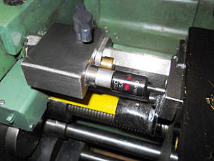
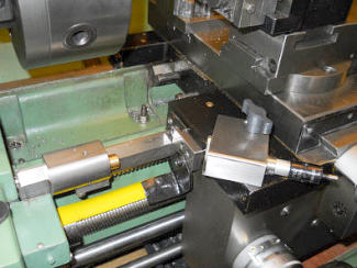
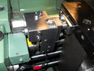
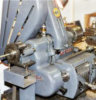
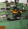
There are often very good reasons and many advantages for having a lathe saddle stop especially when your are making several parts all having the same length size requirements. The most often seen stop mechanism is what I refer to in this article as a 'hard stop', its main function is to provide a consistent and repeatable stop position for the travel of the saddle. This is normally accomplished by fixing the stop unit on the front bed shear such that the saddle 'hits' the stop part of the unit. There is however a potential problem with this approach when absolute accuracy is required simply due to the stop moving as a result of the saddle making heavy contact. It basically all comes down to how 'fixed' the saddle stop is and how much force is used when the saddle hits the stop. So, the saddle hard stop is useful for making repeatable parts when the saddle is fed under manual control and the operator is careful not to 'hit' the stop too vigorously. On my BH600G lathe I have made a basic, light weight stop mechanism which can slide along the front bed way and is fixed in the required position using a single M5 locking screw/handle. There is no additional fine position adjustment micrometer screw as I think this is not needed and in any event fine adjustments can be made using the compound slide. The thought of making inadvertent heavy contact to an expensive micrometer head is certainly best avoided and the compound slide can provide this.‘Soft’ Stop
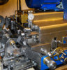
This is the name I use and is purely to differentiate the type of stop and how it is used. I refer to it as 'soft' because the stop mechanism is not achieved by the saddle coming to rest by hitting a fixed stop. The advantage of this type of stop is that it can be used for operations when the saddle is moving under power, such as when screw-cutting or turning to a collar under power feed. The mechanism is very simple and relies on a single bright red LED illuminating when the desired stop length is reached. The operator on seeing the LED illuminate can then disengage the auto feed. Once illuminated the auto feed control lever is dropped into neutral to cease travel. The other prime use is when screw-cutting. In the past I made the George Thomas retracting screw-cutting tool holder which has served me well for a great many years, however judging the precise point at which you operate the lever to retract the cutting tool was always a bit fraught unless there is a run-out channel. After a time, just watching the cutting tool cutting the screw thread during a pass it became increasingly difficult to judge exactly the end position of the thread. This is more problematic if one attempts to not use an end of thread run-out channel and after a time my eyes start to blur just at the crucial decision time! The use of an LED solves this issue as it is an easy event to look out for and is always consistent but it does need some sort of mechanism to operate the LED at the appropriate time - thus the evolution of the soft stop. I always hate having to divert energy into making 'helper' tools such as these and since I have not seen anything available commercially I had no choice but to make a new 'soft stop' to my own design. The prime requirement was for this to be simple, quick to make and accurate in use. Since I already had the 'hard stop' made and operational I decided to use this as the base sliding component with the new 'soft stop' attached to it. The next task was to solve the small but important need to find a suitable LED mechanism and then build this into a unit to be attached to the 'hard stop'. It then occurred to me that I already had a commercial LED unit which was in regular use, an electronic edge finder! This is a professionally made unit primarily designed to fit in a 0.5" collet on the milling machine and has a 0.2" peg to 'find' the edge. On finding the edge an LED illuminates which can be readily seen from several radial positions. Whilst the prime edge normally 'found' with these devices is a side, dowel or hole within the work piece and the 0.2" diameter peg means that on touching the mill spindle is 0.1" away from the edge. As useful as this is the device also can be used to locate surfaces using the base of the peg and this is the part that I decided could be used as my soft stop. At this stage I now had two of the main components, the sliding base unit and the LED indicator unit. Designing a new holder for the LED unit was simple and this attaches to the base slide unit using a single M5 screw with handle. The only remaining problem with this design was the need to protect the LED Indicator should contact be made and the auto feed be inadvertently delayed. The LED unit is engineered for precision and unlike the hard stop it would not take kindly to rough contact or overrun situations. To overcome this the LED indicator fits into its new carrier but is able to slide longitudinally thus when initial contact is made the LED illuminates but should the operator not take immediate action to stop the saddle feed exactly at this point of contact the LED indicator just slides in its holder as it is being gently pushed. In reality this may be around 0.001" - 0.003" depending on the operator action.Design Update with added feature
Recently I have read several articles by model engineers who have experienced the situation we all dread - crashing the cutter into the chuck when under power! Whilst this has not happened to me I accept it is always better to provide preventative solutions which can be applied before things go wrong. Now many lathes have emergency stop buttons, foot brakes etc but when it comes to reacting to a bad situation timing is all important and often this relates to the amount of damage that results. The ideal is to have a simple facility to quickly set up covering various operating situations, such as power feed, screw cutting or simply accidentally moving the saddle into the rotating chuck. In the case of screw cutting I have already made and fitted a special clutch designed by Gray Meek and this automatically stops the saddle determined by a trip so in this case a new indicator is not crucial unless one needs to retract the cutter before the clutch trips. The main area of use is probably when feeding using automatic saddle feed and the auto trip handle needs to be manually operated to stop the travel. If working close to a shoulder or chuck jaws then any delay in stopping the travel may cause a problem and potentially work or lathe damage. With this in mind a new-stop was designed and this incorporates a motor stop after an adjustable delay period. The following description of the new-stop is only feasible if the lathe has other safety features built in which includes a contactor which once tripped to switch off the motor has to be re-set. The use of the previous electronic edge finder has now been retired and is replaced by a new one of similar design but shorter. When the saddle makes contact with the new indicator tip an LED illuminates and if no planned action is taken to stop the saddle movement the motor stops after a predetermined over-run. As before, this new mechanism attaches to the top of the existing sliding hard stop which is mounted on the front bed slide. The delay period before the motor is stopped is usually set to the minimum setting which for example, at 500rpm spindle speed and fine feed trips the motor switch to bring the saddle to a complete stop in 0.5mm (0.020”) however this delay can be increased. Clearly the amount of over-run by the saddle after the trip actuates will vary as determined by the spindle speed and or pitch of feed however these conditions exist in any event and in the absence of this new-stop the over-run and potential damage relies totally on the operator reaction time to stop the motor. The purpose of having this new-stop' was to enable repeatable 'stop' positions to be consistently accurate. This is always assured as the indicator tip always regains an accurate start position as any movement further compresses a spring and thus goes back to the start limit. Associated with this, when the indicator tip moves it also moves a trip actuator for the motor switch which in the free state resets but because the motor switch operates through a contactor the motor remains permanently off until re-set manually. The electrical wiring approach for this new-stop is exactly the same as already incorporated within my lathe. Should the chuck guard, gear door or belt cover be ‘opened’ then power to the motor is switched off. These built in ‘trips’ are ‘daisy-chained’ micro switches connected to a low voltage contactor which in turn trips the main power to an off state. In the case of the ‘new-stop’ another micro switch is inserted into the ‘daisy-chain’. Setting the ‘new-stop’ is very simple. In the case of ensuring the saddle (including top slide etc.) does not crash into the chuck jaws. The saddle is moved to a preferred safe stop position (with allowance for over-run) and the new-stop is set and locked when the indicator tip just touches so that the LED illuminates by sliding the stop. The over-run delay is set to minimum (M6 screw) and this guarantees if for any reason the saddle gets closer to the chuck than planned the LED illuminates and the motor switches off 0.5mm after. For normal power saddle feed the desired stop position is set and the new-stop is set and locked when the indicator tip just touches so that the LED illuminates. When operating in this mode the disengage lever for the saddle feed is moved when the LED illuminates with the over-run delay set to 0.1mm. For screw cutting using a retractable cutter or manual cross slide retraction the required retract position is set and the new-stop is set and locked when the indicator tip just touches so that the LED illuminates. In this case it may be necessary to adjust the over-run delay to provide a more manageable delay time. Should it be undesirable to disengage the leadscrew half-nuts (when cutting metric threads with an imperial leadscrew) and the motor has switched of due to an over-run it will be necessary to reset the switching mechanism to enable the motor to restart. This is done by unplugging the cable (fitted to the new-stop) and plugging in a temporary ‘bridge’ plug thus bypassing the new-stop micro switch. This reset process takes a few seconds to accomplish but has only been needed because of an unplanned mishap. The adoption of this new-stop primarily provides the operator an accurate visual alert when to take action and if for any reason that is ignored then the motor will stop after a predetermined delay thus giving maximum ‘fail safe’ assurance. This ‘new-stop’ is optional and attached by a single M6 cap screw to the existing hard-stop. The wiring cable from the contactor connects to the new-stop using a cable plug type connector which is easily separated. Once removed, the cable from the contactor is terminated by a ‘bridge’ plug to maintain electrical integrity. Update: Since I have introduced an inverter and 3phase motor the original contactor is redundant however the inverter has a built in emergency stop facility and thus the daisy chain approach is wired into this resulting in the same motor stop. The inverter also requires the start to be pressed if the emergency stop or normal stop is activated thus the same as a NVR setting. The new-stop is designed to provide an accurate limit stop guide with an additional built in fail-safety feature which hopefully is never used.GWH Engineering
creative engineering in a home workshop