

© all rights reserved G W Howe 2017 - 2020
Projects
Project to design a quick withdraw mechanism on the BH600G lathe.
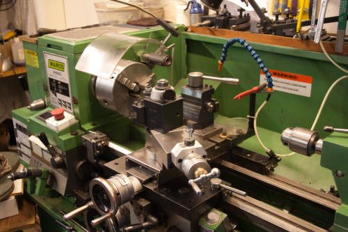
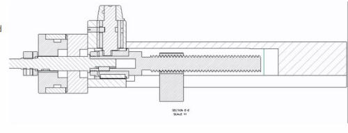
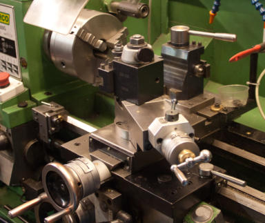
This project was a natural addition to the previously made Screw Cutting Clutch unit designed by Gray Meek both of which featured on the Hardinge lathe. George Thomas had designed a similar mechanism to fit the Myford Super 7 and I had previously made the tool post attachment he designed for the Myford ML7. Based largely on the GHT design I designed a similar withdraw mechanism attempting to make use of the current BH600G compound slide parts. The main challenge was the making of a new feed screw and nut with Acme thread but this was not in practice a problem. I was going to make the nut similar to that originally fitted but it was made from a round bronze bar fitted vertically with a cross threaded hole. As such the area of thread contact was much reduced. To improve this I made a housing for the bronze out of steel and press fitted a bronze bush which I was initially going to tap. In the end I dispensed with the tap and made a boring tool with an Acme shaped HSS cutter attached. Although this was somewhat fragile with careful working it produced the thread and the previously made feed screw fitted to provide a better result than the original combination. A tap might have been a best bet method but considerable force is needed to cut an Acme thread so I thought it better to cut some partial depth threads and finish with a tap. In practice I managed to cut to the required depth and the feed screw fitted ok. The main mechanism largely follows that designed by GHT and this provides for the complete mechanism to attach to the compound slide but in so doing this approach requires the main feed screw, which will remain stationary during the withdraw operation, to have a two part feed screw such that the ‘handle’ end can slide. The amount of slide is required is a minimum 4mm and this when screw cutting should cater for the majority of threads. Using this method the existing handle, graduated disc and bearing housing unit is retained. The main feed screw is fitted to a separate sliding housing and has a thrust collar to eliminate any free longitudinal play. The withdraw action is done using a crank and die block which when rotated about 130 degrees provides 4mm of movement. GHT in his design incorporated a bush for the crank which has its outer diameter made slightly eccentric. This enables adjustment to ensure the main slide driven by the crank and die block lock for normal use with no end play. The main housing for the mechanism is made from aluminium 3” diameter bar which is easily available but I have found that any sliding or rotational parts made of steel do not work well with aluminium and so for this reason two steel bushes were press fitted into the aluminium housing. The final task of assembly and fitting to the existing compound slide is relatively simple though care must be taken to mark out the drill positions to attach the aluminium housing. This is best done by assembling the complete mechanism and using the feed screw advance it into the feed nut until the aluminium housing mates to the compound slide end face. The two attachment holes can then be marked and subsequently drilled and tapped. In my case I found I had not allowed for sufficient adjustment to prevent binding when turning the handle but this was easily remedied by drilling the two M6 clearance attachment holes in the aluminium housing with additional clearance. Unfortunately, getting prefect alignment when marking the attachment holes is not that easy but as I found making the holes slightly larger provides small alignment corrections. In use the completed assembly to the compound slide moves freely when rotating the handle and locks the unit in the home position for normal use. This mechanism now provides a simple and reliable working method when screw cutting and eliminates having to continually having to reset the dials to withdraw the cutting tool. A free set of drawings in A4 PDF format are available on requestGWH Engineering
creative engineering in a home workshop


