


© all rights reserved G W Howe 2017 - 2020
Projects
Project to implement an inverter drive for the BH600G lathe
GWH Engineering
creative engineering in a home workshop
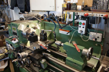
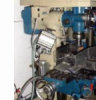
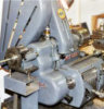
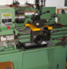
The BH600G is a basic belt driven lathe with back gear
arrangement exactly the same as in the Myford. The only
problem is the changing of the motor belt from large to small
pulley was difficult as I had no access to the rear of the lathe.
The best solution is to incorporate an inverter drive unit which
then gives easy speed changes. Where very slow speeds are
required it is best practice to allow the inverter to operate at a
medium to high frequency to prevent over heating of the
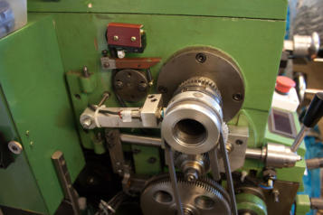
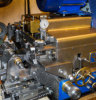
inverter. The change of spindle belts is quick and easy and for
very slow speeds the back gear is used. I normally have the
motor pulley drive set to high speed and the spindle pulley to
middle which at full frequency gives 900rpm.
Installation of the inverter unit is relatively straight forward. The first stage was to remove all of the electrical contents from the
existing lathe cupboard at the rear. I had started to experience some intermittent contact failure with the original set-up so it
was probably only a matter of time before the contactors failed completely. The cupboard is now used to hold the mains feed
to the inverter including a no volt release switch with LED incorporated into the door. Other basic transformers for the lighting
and suds pump are now in the box and a connect strip to include the safety switching.
I was keen to continue the BH600G safety concept which prevented
the motor running if a door was open etc and the use of an
emergency stop button near by. This was relatively easy to set up
as the inverter I bought had a safety option which could allow a set
of control switches daisy-chained together to ensure all was correct
before the motor started. The inverter incorporated a no re-start
following the stop control so this added exactly the type of safety
switching needed.
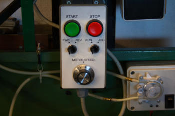
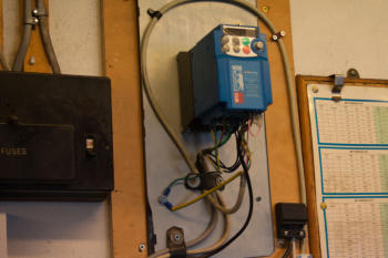
I bought from the inverter supplier their control unit which
provided start, stop, forward, reverse, run and jog controls. The
best place to position this control unit was based on use to be at
the RH end of the lathe and to the back so it was fitted to the rear splash guard.
The safety features as mentioned were all inter-connected so the
lathe motor would not start unless all were in the safe position and
in the event any one was, say in the case of the chuck guard, raised
the motor would stop and remain stopped unless made safe and
the control unit start button pressed.
The safety switches include:
chuck guard
pulley top cover
gears door
carriage lever previously now stop only
carriage stop
Emergency Stop
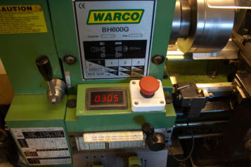
The emergency stop button is now at the front LH side and I have added a tachometer display. The tachometer pick-up is at the
rear of the spindle.