


© all rights reserved G W Howe 2017 - 2020
Projects
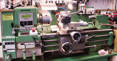
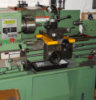
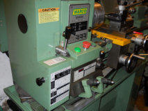
Project to design a screw cutting clutch based for the BH600G lathe.
Introduction
The Screw Cutting Clutch mechanism originated with the Hardinge lathe and was used to simplify the cutting of machine screw threads without having to continually stop and start the motor when reversing. The type of leadscrew (metric or imperial) determines the way in which threads are cut however the following article assumes the lathe with an imperial lead screw. A metric lead screw lathe conversely presents the same conditions but with a bias towards metric threads.Imperial Threads on an imperial lead screw
With most lathes designed specifically for cutting imperial thread ranges there is usually a thread engagement indicator dial mechanism positioned near or on the saddle. Imperial range machines have a leadscrew which has a prime number of threads such as 4, 6 or 8 threads per inch. The conventional screw cutting procedure is as follows: set the cutter to start depth, engage the screw cutting lever on a known indicator dial position, machine the thread to its full length then disengage the leadscrew engagement lever, withdraw the cutting tool, and manually wind back the saddle to the start of thread, reset the depth of cut and repeat the process until full depth of thread had been reached. During this time the motor would usually remain running.Metric Threads on an imperial lead screw
Using the same lathe with an imperial lead screw presents a few problems when cutting metric threads because the indicator dial graduations are not an exact multiple of the metric thread pitch. The upshot of all this is that the indicator is of no value so when the screw cutting lever is engaged it has to remain engaged until completion of the full depth thread. Although the basic steps are the same as above the only way to ensure the lever remains engaged requires the motor be stopped at the end of a forward cut and then restarted in reverse to the start position. This constant need to stop and start the motor is not only very time consuming but also wearing on the motor and control switching. The solution to this problem is the adoption of a clutch to automate the reversing of the lead screw whilst the motor is running, i.e. the motor remains running in one direction only during the complete process.Screw Cutting Clutch Concept
The above description hopefully identifies the need for a clutch mechanism especially in the case of metric threads using an imperial lead screw. However, once a clutch is fitted then the whole process of machining screw threads is very much simplified since the engagement lever remains engaged and the clutch automatically provides the ability to reverse to the start of a thread and importantly, remain in exact synchronisation for the thread form being cut.Screw Cutting Clutch for the BH600G Lathe Design
Via a mutual contact with whom I had discussed the design of my Sunderland Gear Machine, he introduced me to Gray Meek an engineer of much experience who amongst other projects had previously designed a screw cutting clutch similar to that used on the Hardinge lathe. I think his original design was for the Myford S7 as he made two prototypes for customers some 20 years ago but despite these prototypes being very successful and actively used further promotion of the design remained largely hidden. That was until Gray resurrected it for an article in Engineering In Miniature magazine and a book he was about to publish. Gray was keen to widen the scope of his clutch design to include a variety of lathes and I provided him some dimensional information relevant to the Myford ML7. Later I bought a new Warco BH600G lathe (also known as the G9249 in the USA) and so asked Gray if he would further expand his design to include my new acquisition, which he readily agreed. The BH600G is a substantially larger lathe than the Myford but has a conventional gear train and Norton style gearbox plus the leadscrew was 8tpi so to cut metric threads demanded his clutch design. Over a period of a few months the design appeared and although the BH600G looks like a larger version of the Myford ML7, the design of the clutch was very different, though based on the same working principles. Gray told me that every lathe presented new problems, design-wise, but so far he had always managed to find a solution. To make matters worse for him I requested that he incorporated a facility to manually disengage the clutch from use by a simple lever. The reason for this request was due to the noise using the gear train especially at high speed running of the tumbler gears. With the clutch design both ‘tumbler gears’ operate at the same time and I guessed it might get even noisier! Thread cutting, as I see it, is mostly done at low speeds and in the case of the BH600G probably using back-gear. The lowest direct drive speed is 300rpm which is I think too fast for comfort especially on short thread lengths so my request was, for me, a crucial requirement. A few weeks passed by an Gray casually mentioned that it was now sorted using an eccentric to rotate the driving tumbler gear out of engagement with the spindle gear. It seemed this was not his main problem however as the BH600G had several obstacles (spindle bearing cover) to avoid and eventually, and ingenuously, he devised a method for the main control shaft of the clutch mechanism to pass through the centre line of the main gear shaft. With this solved he passed over the basic drawings to me which omitted several of the ancillary parts such as the auto link mechanism for stopping and starting as this was, for him, difficult to design for a lathe he had never seen! At this stage I want to pay tribute to his design and engineering skills however, on completing the clutch he casually remarked that he had some worries about it and hoped it would work out! Well it did thankfully.Phase 1 Design and Manufacture
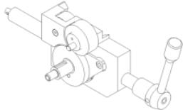
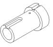
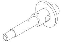
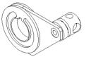
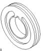
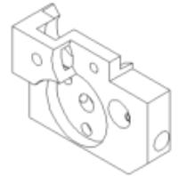
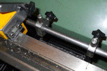
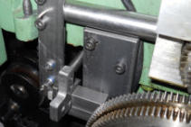
The design for the main clutch mechanism belongs to Gray Meek and as such I am unable to provide any drawings but I know he will provide these or give me permission for me to help on this front if they are requested via me. On receiving Gray’s drawings I made my own set of drawings by modelling. This helps me understand the task in hand and also proof the dimensional accuracy of the parts. All dimensions provided by Gray proved to be accurate but a few minor modifications had to be incorporated later on assembly. These modifications are since updated in the source drawings. The linkage and application of this to the BH600G is of my design and thankfully a very simple task. The starting point for this design is to make the gears. Having my own Sunderland based gear cutting machine I was able to make these despite the gears being at the limit of its scope. The gears are all 1.5 Mod, 20 degree PA. I decided to make the two ‘tumbler’ gears (25t & 30t) from Delrin as this has shown to be remarkably strong and quiet running. As an aside, when making these gears I was able to see my gear cutter working in an unstressed condition since Delrin is a soft plastic material and this led me to identify a solution to a problem on the machine which had been bugging me for over six months! With this new-found knowledge, work stopped on the clutch and the Sunderland was stripped and a new module added which has proved to be very effective. The other two gears are cut from steel and 40t. These have a phosphor bronze bush pressed in and a recess on one side to house the clutch ring. The main gear shaft is then made, I used a hard alloy steel because I had been given some and the Myford did not like cutting it but the bigger lathe managed it well. Hopefully the alloy steel will provide good wear resistance but is not essential. Fitted to the main shaft is an outer rotating shaft which is keyed for the clutch ring and output gear to the main gear train. This was made from steel but, and a change to Gray’s design, I included a phosphor bronze bush. This was actually easy to incorporate by initially force-pressing a solid phosphor bronze rod into the rough turned work and then boring/reaming the bronze to shaft size. Next the clutch ring which is double sided with a part recess and an outer groove for the actuating lever-plate. This requires some care in manufacture and takes time to machine using the rotary table on the milling machine to machine the part-recesses. At this stage a parcel arrived from Gray which was the aluminium billet needed to be carved up to house the mechanism. I was very thankful to Gray for providing this as I think, getting this locally would have been impossible. The modelled drawings I had made helped me understand how best to machine this block especially so as there was no second chance should a mistake be made. Essentially, the block is first machined on the rear side, then the front side and lastly milling off the redundant metal. I planned the process to be done using my DRO on the milling machine but it decided mid-way to stop working and it is only then that the virtue of a reliable DRO becomes evident! Despite this set back, the machining was finished and offered up to the lathe where it became evident it was a very tight fit due to the spindle bearing housing. This required re-machining the recess to very slightly enlarge it. With some of the smaller ancillary parts made a full trial assembly can be made. I think anyone contemplating making this clutch unit must accept that it will require time and patience. The clutch ring is operated by a lever-plate which in turn is operated from a shaft (or shafts). The movement is controlled by a small shaft which fits to the main aluminium body and again I added a phosfor bronze bush for this to slide on though Gray is of the opinion it is ok without a bush. This shaft has a ‘V’ ring machined into it which acts as an indexing point using a spring and ball to locate the centre position. It was Gray’s view that whilst the ‘V’ used on the other designs it might not be best placed and some alternative position for controlling the centre and left/right positions of the clutch would have to be remote from the main block. This proved to be partially correct and in practice I designed a set of two opposing collars fixed to the operator handle shaft with three spring loaded balls to locate (index) into their appropriate ‘V’ set in the opposing collar. All this was to some extent trial and error but eventually a solution was found that worked but it also needed the original ‘V’, ball and spring on the inner part to prevent localised movement. Fitting these collars and setting the precise location of the ‘V’s for the spring loaded balls is not simple and takes time however a process has now been devised should any builder experience problems on this front. The other thing Gray understandably omitted from the drawings was the linkage mechanism. This linkage fits to the rear of the operating shaft such that when moved it will push the clutch out of engagement for both directions of saddle travel. The mechanism I designed comprised a rear-end lever, push rod, two control stops and saddle stop. The rear end lever was initially a problem as there was little room to fit any lever as is would foul the gear cover. Eventually a fabricated design was arrived at which only required a very minor fold to an inner edge of the gear cover to allow the cover to open fully as before. The push rod was a length of 0.5” steel bar with a flat milled on one side and this runs the length of the lathe bed at the rear. The extreme end, near the tailstock, needed some sort of support for the push rod and this was done utilising the already fitted support bar on which the splash-back is fixed. The two adjustable stops slide along the push rod and are fixed as appropriate with a cap screw that clamps a bent ‘U’ shaped spacer against the rod flat thus eliminating any possibility of raising burrs. Finally, the main stop control arm was fabricated from steel plate and this fits to the top of the cross slide in the ‘Tee’ slot with adjustment to cater for different sizes of thread outer diameter. This is not a easy project but well worth the effort because from now on machining metric or any other threads is simple!
Phase 2 - Living with the Screw Cutting Clutch
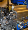
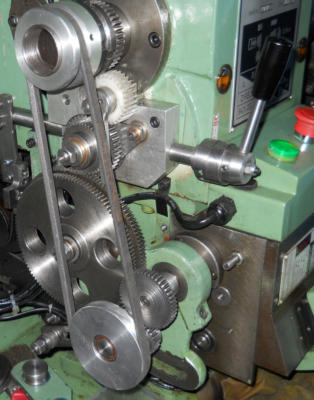
Right from the start of this project I knew just how beneficial having a screw cutting clutch would be, however it also brings a problem with it. The design of the clutch uses multiple gears (similar to the standard tumbler gears) but in this case both are running at the same time. A similar problem arises when using the normal tumbler gear arrangement when both gears are engaged (such as on a Myford) and this too results in quite a lot of running gear noise. Myfords solution came with the use of a Tufnol gear however with a larger lathe, such as the BH600G, larger gear teeth amplify the noise quite a bit. I made both the 25 and 30 tooth gears from Delrin which helped a little. Because my workshop is directly below the main living room it is best if any noise is kept, as far as possible, to an acceptable level. I had my concerns during the early days when I discussed the design requirements for the screw cutting clutch with Gray Meek and it was because of this I asked him to incorporate the lever to enable the clutch gears to be disengaged from the main drive. That may seem to be the perfect solution but the gear drive also provides feed into the Norton gearbox for both screw cutting and power feed to saddle and cross slide! As far as I am concerned, when cutting threads, this is done in almost every case using low speeds, and typically, as in the case of the BH600G, provided with back gearing. These speeds range from 50 to 220rpm the lower ones being most appropriate. Unfortunately, the same cannot be said for general power feed which needs to cover the complete speed range. The use of the new clutch gears running at higher speeds will definitely create problems from those up above, not to mention unwanted and unnecessary wear! Running the screw clutch at 300 rpm was just acceptable but what I wanted was the best of both worlds - the ability to machine screw threads and also have peace and quiet whilst running with power feed at higher spindle speeds. The solution was to design and make a belt drive when not screw cutting, which is of course most of the time. Seen in the photo above the new belt feed and mechanism is set up and the screw cutting clutch above with its disengagement lever down (just behind the belt RH side. The belt drive mechanism is easily removed when screw cutting needs to be done by a single nut! More details of this can be seen in this project article.Phase 3 - DRO causes a rethink
GWH Engineering
creative engineering in a home workshop

There was however a major consequence of fitting this new DRO scale and that was the arrangement I had used to operate the trip
mechanism for the Screw Cutting Clutch was no longer practicable. For some time I had wanted to move the trip mechanism away
from the rear of the bed as setting the trips was inconvenient but now with the DRO scales close by I did not want to be making
adjustments and accidentally damaging the DRO unit. No matter, this was a problem I always knew would at some time need
resolving.
With the DRO successfully fitted and working as
expected I now needed to resolve the Screw Cutting
Clutch trip mechanism. I
decided that although it could be modified to remain
at the rear of the lathe bed this was far from ideal and
I never liked having to
reach over to make adjustments to the trips blindly.
The better solution was to move the mechanism to
the front of the lathe bed and in the process
incorporate a safety device to ensure the screw
cutting trip lever was fully disengaged when not not
doing screw cutting tasks.