


© all rights reserved G W Howe 2017 - 2020
Projects
Project to design a rear toolpost for the BH600G lathe.
Rear Tool Post
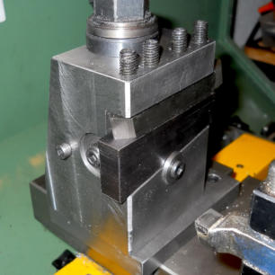
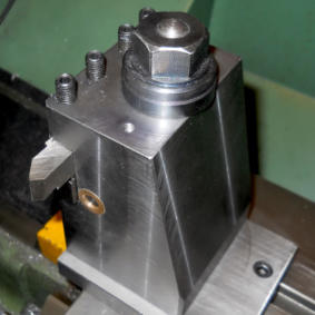
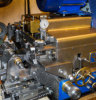
Yet another Rear Tool Post implementation, but this one is a bit different. I decided I would like a rear tool post on the BH600G (12” swing lathe) primarily for convenience. Many advocate, myself included, that for parting off operations a rear tool post with the cutter inverted makes a lot of sense as it is not associated with any movement from the compound slide. Of course other tools can be used in a rear tool post but for me the parting off tool is top of the list. There are literally a lot of different designs around, one being the QCTP which it provides rapid tool changing but also needs an additional tool holder. Whilst this design is clearly advantageous from a speed point of view I prefer to have the rear tool post primarily used for the parting off tool. A great design feature of the QCTP is the easy adjustment method to set the cutter to the correct height without the use of shims. Whilst contemplating the various designs needs it occurred to me that height adjustment could be achieved by using a sliding wedge under the cutting tool, however I was unsure how successful this approach might be in practice. A quick search on the web revealed an almost exact version of my sliding wedge idea made and used by Hardinge and so I decided this was not only feasible but clearly very desirable. A lump of 4” diameter steel 4.1” long came my way and is a somewhat formidable piece of steel however it has always been my belief that when it comes to a machine tool rigidity mass is very beneficial. With both ends of the bar faced and centre drilled, a 0.5” diameter hole was drilled for the post. The next task was to mill the round bar to change it into a square sided block. Whilst this may seem a major machining task the use of a carbide insert face milling cutter soon removes the metal. The work piece was then transferred back to the lathe four jaw chuck to bore a cross hole with a recess (1” diameter x 1” deep) and drill a through-hole for a pressed-in pb nut tapped 3/8” BSF. This would be for the screw mechanism used to adjust the wedge position. Then another re-location in the four jaw to machine the wedge ‘keep’ washer and then back to the mill to make the slot for the sliding wedge with an included angle of 8 degrees at the bottom edge. Finally the block was further reduced to form a rear sloping side. The ancillary parts included a base plate, post, nut and washer, wedge, wedge control screw, spacer and keep assembly. The wedge in its ‘home’ position in its initial design (see photo opposite) allows for 0.5” square cutters and about 0.125” height adjustment. I find the most convenient cutter is the bevel as this is needed so many times when making most parts. The crucial fine height adjustment remains as before and is done by the positioning of the sliding wedge as appropriate by turning the control screw. This finished Rear TP is certainly robust and able to take various cutting tools, all of which are inverted so that the spindle direction remains as for normal turning. The rear tool post remains permanently attached to the cross slide and when not in use it is rotated 90 degrees which provides plenty of clear space for normal lathe turning operations.GWH Engineering
creative engineering in a home workshop