


© all rights reserved G W Howe 2017 - 2020
Projects
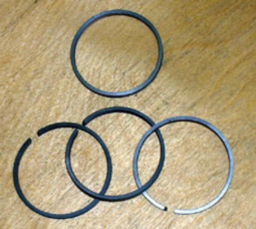
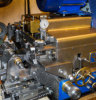
Project to make cast iron piston rings
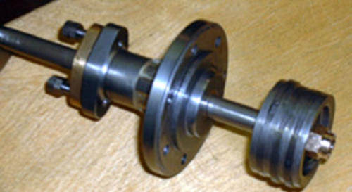
Making of piston rings is not that difficult! In the process of building my model locomotive, "Neptune" the drawings called for 6 cast iron piston rings. Although these were available from commercial suppliers they do cost a small fortune, so I decided to do some research from the wealth of experience out there in the model engineering fraternity and was encouraged by other successes. I managed to find, via the web a very useful link all about piston ring manufacturing as might be undertaken by a model engineer. This article was written for the Model Engineer and describes views put forward by Prof. Chaddock and Tom Walshaw (Tubal Cain). The rings needed for my 'Neptune' model are 1-3/4" diameter with a cross section of 1/8" by 1/16". Since I was making my rings an added advantage was for me to make any small changes in dimensions to suit my cylinder bores. Despite my best endeavours, one cylinder was exact and the other was 0.0015" over size! This however was no longer a concern as I had made the pistons to match each bore as precisely as I could without undue friction and now I could also make the rings to fit exactly. I used some 2" diameter continuous cast iron stock to make the six rings. As I had only just enough cast iron available and was unsure how successful making these would be I decided to make the first three and then if all went well make the other three. I was particularly concerned that one or all might break when expanding them over the piston. Following the advice given in the Model Engineer article a start was made by turning the cast iron stock to OD +0.004" and using a 1/16" thick parting off tool made three grooves 0.070" deep and a few thou bigger than 1/8" apart. This is so that each ring would be a few thou bigger than 1/8" finish size and then later finished to an exact sliding fit in the piston recesses. By making the ring grooves all the same depth when it comes to boring the internal diameter each ring 'falls' off onto the boring bar as the cutter breaks into the groove bottom. For each new ring a diagonal cut was made with a fine hacksaw blade so that the ring could be later expanded. The article recommends a wedge, four times the ring thickness, to be inserted to expand the ring during heat treatment. With some caution and fully expecting the rings to snap they were prized apart and the wedge was inserted and gripped firmly in place. Three 'wedged' rings were now clamped between two steel washers and gently heated to ' just visible' red heat for about 15 minutes and left to cool in air. Once the rings were cold, I was much relieved that with the wedge removed they held the same gap. Each ring was now carefully de-burred on the ID and the sides brought to an exact sliding fit in the piston grooves by using emery cloth on a flat base. To finally machine the OD to exact size and ensure it is concentric I followed the advice given and made a sleeve and turning jig. I decided to turn each ring individually which I think is a good decision as any mess up only spoils one ring. I have to admit that using the sleeve and jig proved to be difficult and getting the sleeve off, after clamping, was sometimes 'sticky'. Despite my trials the ring seemed unable to run concentrically enough to allow just a skimming cut of a thou or less. Thinking about this, but not yet tried, next time I shall make rings and not use the sleeve. By closing the ring by hand to leave the original 'saw blade' gap and then clamping should produce similar results. Using a four jaw chuck the ring can then be centred to give the minimum run-out for the final truing cut. Hopefully this approach will allow better 'feel' and setting of the ring. The moment of truth had arrived and with much care the rings were expanded over the piston and slid into the respective grooves. I used some fine steel shim to help the first two rings reach over the first recesses. To my amazement and delight no breakages. Job done! Initial compression tests show that the rings are doing their job and will continue to do so after running in. The pistons and rings have been assembled in their respective cylinders and by hand moved back and forth to 'lap' to size. On further inspection it was interesting to see the lap marks on the rings and fortunately there was only one ring which showed some 'un-lapped' surface (about 10%). I had experienced some difficulty on this particular ring and rather than take off too much during the truing process I left it with a small amount not skimmed. This was more than 10% and thus the lapping will in time probably sort it out, in any even for my purposes 10% is of little consequence as their are two additional rings to negate this. update I have just finished making some rings which are 0.625" od and 0.030" section. The problem as before is the final skimming process to bring them to correct size. The recommended method is to mount each ring between guides and grind or turn off the excess but for rings of this size I found this impossible. The method I eventually adopted proved to be very successful and is easy to do. Make a cylinder about 1.5" long bored and lapped to exactly the required finished od size. This can be of any material and in my case I used mild steel. Make a short (1" long) pressure bar about 0.010" down on cylinder bore diameter and another bar of brass about 3" long to be a sliding fit to the cylinder. The ring to be sized is placed inside the cylinder and a little fine grinding paste smeared inside. The brass bar is inserted part-way into the cylinder to touch the ring and the short bar is inserted at the other end of the cylinder and used with light hand pressure to hold the ring in place. The cylinder is now moved back and forth with rotation several times. The ring is constantly re-positioned and the lapping process repeated until the ring shows 100% evidence of lapping. The ring is now exactly to diameter.GWH Engineering
creative engineering in a home workshop