


© all rights reserved G W Howe 2017 - 2020
Projects
Project describing the making of a jig to turn balls on the lathe
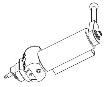
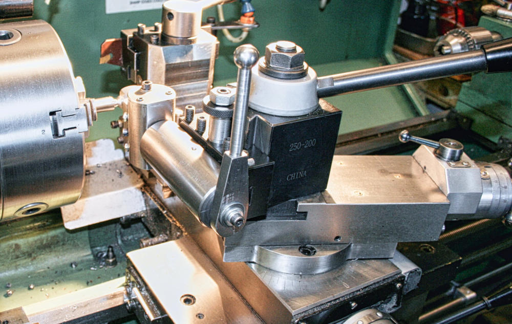
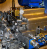
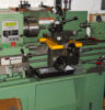
I made a ball turning tool many years ago to fit on my ML7 lathe but since now also having a BH600G Warco lathe I decided to make a new ball turning tool of a different design to that on the ML7. The new design is largely made from mild steel bar stock and is substantially bigger and more robust in its operation thus providing a better and controlled surface finish. The design also allows for the tool to mount to a quick change tool post holder using a spacer to ensure it is set to lathe spindle centre height. The main control is a rotating lever which faces the operator and enables balls to be turned up to 28 mm diameter. As can be seen in the sketch, the main body of the jig is made from round ms bar stock with a reamed centre hole. A spindle fits to this body with a rotating handle which directly faces the operator. The other end of the spindle mounts to another round bar in the perpendicular plane and this has a dovetail machined in it for a cutter slide unit. The cutter slide unit moves in the dovetail by means of an M5 cap screw and a bronze nut within the vertical body. A gib and two M4 set screws and an M4 cap screw provide a good sliding movement. The cutter is a HSS round bar with the cutting edge approximately 2mm wide and radius. The cutter is mounted at an angle and from this the required shape and relief angles can be decided. When making ball handles the stem joining the ball can be catered for by machining the bar blank with a 8 - 10mm groove preceding the ball outer diameter. It is best to make the ball od. and length 0.2- 0.4mm larger. When mounting the bar blank to the lathe chuck it needs to extend from the jaw end such that the groove can be accessed by the rotating cutter tool. Some additional clearance is also needed for safety purposes but overall the extension of the bar is around 50mm. Once set up in the chuck and the cutter tool aligned the carriage should be locked. The cutter tip needs to be set on c/l when the operating handle is vertical and at mid position of the ball to be formed. This is easily tested by checking the cutter just touches the edges (groove, bar end) equally. Feed is applied by turning the M5 cap screw a small amount and the operating the handle back and forth until the ball required diameter is reached. A set of A4 drawings are available hereGWH Engineering
creative engineering in a home workshop