


© all rights reserved G W Howe 2017 - 2020
Projects
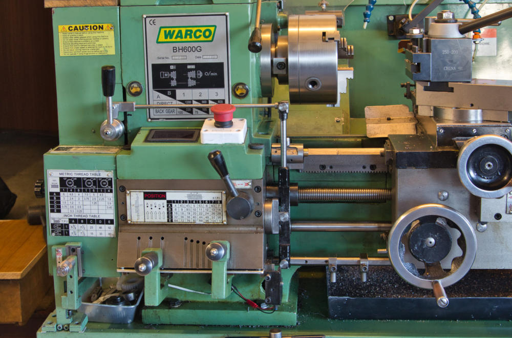
Project to fit a DRO on the BH600G lathe.
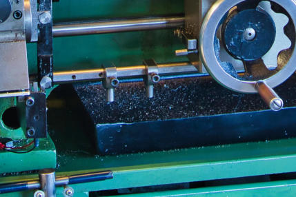
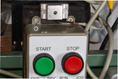
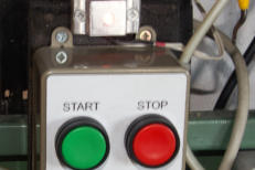
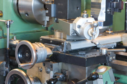
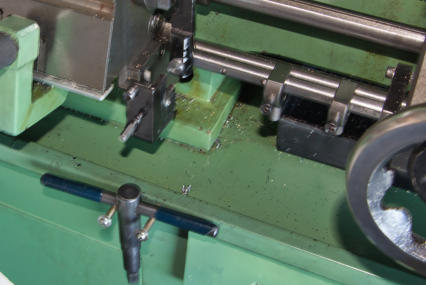
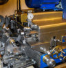
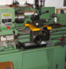
This project was a natural addition to the BH600 lathe and, although for me a luxury, it provides an accurate use of the ‘X’ and ‘Z’ axis. I decided to opt for a general kit supplied by MachineDRO UK, which utilizes magnetic scales rather than the optical ones. The main advantage was the magnetic scales and housing is a better fit to the cross-slide and also the magnetic scale can be easily cut to length required. I decided to mount the DRO display unit bracket arm to the back wall behind the lathe swarf guard and towards the tailstock end. Although not the conventional way normally over the headstock because as a right handed person it made sense to make adjustments with my right hand, plus the control unit for the lathe start, speed etc. is also, in my case, fitted towards the right end of the the back swarf guard. The lathe is fitted close to a rear wall in my workshop and I was not wanting to move it, so fitting the rear scale to the lathe rear side of the bed was a bit of a challenge. That said, although the bed fitting surface was as cast and not machined flat, fitting the aluminium backing strip was relatively easy. The scale backing strip is an extruded shape so that the magnetic scale slides in to the centre part and has a thin stainless steel cover. The assembly is quite rigid and to make life easier I only used two mounting screws, one at each end plus spacing washers. This made the alignment task very simple and since the read head is not in contact with the scale then this fitting was more than adequate. The fitting of the read head was again no problem though I found the brackets supplied less than ideal but this was a minor task to alter. A protection top cover keeps the scale secure and protected from dirt, suds etc. Fitting the DRO scale to the cross slide was very straight forward as it was fitted to a machined surface. Once again, the supplied kit parts for the read head attachment were totally unsuitable. This was not a major problem and instead of using the supplied aluminium castings a steel plate arrangement was made and this included a ‘stop’ bolt to prevent the tailstock crashing into the DRO scale. The photo shows the cross-slide scale fitted and also the quick retract mechanism on the top -slide. There was however a major consequence of fitting this new DRO scale to the rear of the lathe bed and the arrangement I had used to operate the trip mechanism for the Screw Cutting Clutch was no longer practicable. For some time I had wanted to move the trip mechanism away from the rear of the bed as setting the trips was inconvenient but now with the DRO scales close by I did not want to be making adjustments and accidentally damaging the DRO unit. No matter, this was a problem I always knew would at some time need resolving. With the DRO successfully fitted and working as expected I now needed to resolve the Screw Cutting Clutch trip mechanism. I decided that although it could be modified to remain at the rear of the lathe bed this was far from ideal and I never liked having to reach over to make adjustments to the trips blindly. The better solution was plain to see and was to move the mechanism to the front of the lathe bed. Fortunately as it turned out, since I had previously fitted a speed control inverter which had a remote control unit I no longer used the lathe start /stop, forward /reverse control handle fitted to a fixed longitudinal rail just below the feed drive shaft. However, since this rail was non functional it could now be incorporated into the new design. So, the screw cutting clutch lever now has a horizontal rod attached with pivot pins at both ends and the RH end attaches to the top of a vertical ‘rocking’ arm, This vertical ‘rocker’ arm can move about a mid position (set to give a 3:2 top:bottom) approximate ratio. At the bottom of the rocking arm is another horizontal rail pivoted with a pin and at the other end slides in a block housing which is now fixed to the unused lathe switch rail near the tailstock end. Two trip disks (shaped to pass under the apron) are clamped as needed along the sliding rail, one for forward control and the other for return. The activating trip arm is a simple lever attached at one end to the lathe apron and rotated into position as needed. The photo shows the trip lever (just left of the hand wheel) set horizontally in the ‘not in use’ position. Also an M4 screw fixes to the apron on which the trip lever rests, this ensures the lever does not accidentally rotate down into the active position. Operationally, when the trip arm is rotated to point down it will make contact with the forward and reverse trip disks and then on contact push the sliding rail forward or backwards as appropriate when the carriage unit moves. The sliding rail then causes a vertical rocking arm to rotate a small distance which in turn causes the top rail to move and rotate the main screw cutting clutch handle arm until the clutch disengages. (note, the rocking lever ‘magnifies the carriage movement and this causes the screw cutting clutch to disengage more accurately). From previous practical experience there is always a chance to forget to rotate the trip lever out of engagement after a screw cutting task is completed. This obviously is essential otherwise it will cause a lock-up situation and potential damage. A simple yet very effective solution has now been incorporated as follows. The trip lever can only rotate downwards after the ‘safety’ M4 screw has been removed from the apron (just left of the hand wheel). and is then repositioned to a bracket attached to the gearbox end (just above the chuck key). On screwing the M4 screw into the bracket it, via an attached micro switch, causes an LED light to illuminate next to the lathe start control button. Thus if all screw cutting is finished and the LED remains illuminated then it is obvious the trip lever needs to also be rotated back and the bolt re-attached to the apron. The bolt in the apron also acts as an additional safety precaution since the trip lever even if knocked cannot drop down unless the screw is removed. If the trip lever is set in the horizontal position, an LED indicator light fitted above the start/stop control is not illuminated, however when the M4 screw is removed to enable the trip lever to rotate to the down (engage} position and is transferred to a ‘keep’ plate fitted to the end of the screw cutting gearbox it operates a micro switch which illuminates the LED as shown above the Inverter control panel in the second image. Since the operator has to press the green motor start button to start the lathe, this provides an immediate indication as to the trip lever position and if not doing screw cutting, then the trip lever needs to be rotated upwards and the M4 cap screw removed from the ‘keep’ bracket and replaced into the apron. Whilst this may seem over the top, when I previously hat the trip mechanism fitted to the rear of the lathe bed on more than one occasion I started the lathe motor and on engaging normal cutting feed feed suddenly realised the trip lever was still active. if the trip lever engaged a trip the carriage could now only travel a short distance and it would lock up resulting in something the has to give! Fortunately, I never previously experienced a major problem but on several occasions it was a close call!GWH Engineering
creative engineering in a home workshop